Basket: £0.00
View Basket »
Open to Trade & Public
Professionals to DIY
Professionals to DIY
CUSTOMER SERVICE
We're Online 9am - 5pm
We're Online 9am - 5pm
FREE DELIVERY
On Orders Over £30
On Orders Over £30
Published: 03/05/2024
The Ultimate Guide to Clutch Kits and Dual Mass Flywheels: Enhancing Your Driving Experience
Introduction: In the world of manual transmission vehicles, two critical components stand out for their role in transferring power from the engine to the wheels: clutch kits and dual mass flywheels. These components work in tandem to ensure smooth gear changes and efficient power delivery, contributing to an enjoyable and responsive driving experience. In this comprehensive guide, we'll dive into the realm of clutch kits and dual mass flywheels, exploring their functions, benefits, and maintenance tips to help you make informed decisions for your vehicle.
Understanding Clutch Kits: The clutch kit is a vital component of manual transmission vehicles, enabling the driver to engage and disengage the engine's power from the transmission. Here's how it works:
-
Clutch Assembly: The clutch kit consists of several components, including the clutch disc, pressure plate, release bearing (or throwout bearing), and sometimes a pilot bearing or bushing. These components work together to transfer power from the engine to the transmission by engaging and disengaging the clutch.
-
Clutch Engagement: When the driver depresses the clutch pedal, hydraulic pressure or mechanical linkage disengages the clutch, allowing the engine to spin independently of the transmission. Releasing the clutch pedal re-engages the clutch, transmitting power to the transmission and ultimately the wheels.
-
Friction Material: The clutch disc contains friction material on both sides, which grips the flywheel and pressure plate when engaged, transferring power from the engine to the transmission. Over time, the friction material wears down and may require replacement as part of routine maintenance.
Understanding Dual Mass Flywheels: The dual mass flywheel (DMF) is a specialised type of flywheel designed to dampen engine vibrations and smooth out power delivery to the transmission. Here's how it works:
-
Dual Mass Design: Unlike traditional single mass flywheels, which consist of a single solid disc, dual mass flywheels feature two separate masses connected by a series of springs or dampers. This design isolates engine vibrations and reduces transmission noise and harshness.
-
Vibration Damping: As the engine generates power, it produces vibrations and torsional loads that can impact drivability and comfort. The dual mass flywheel absorbs and dissipates these vibrations, providing smoother acceleration, reduced gear rattle, and improved clutch engagement.
-
Enhanced Durability: Dual mass flywheels are designed to improve drivetrain longevity by reducing stress on transmission components, such as the clutch and gearbox. By minimising shock loads and vibrations, DMFs help prolong the lifespan of critical drivetrain components.
Benefits and Maintenance Tips: Investing in quality clutch kits and dual mass flywheels offers several benefits, including smoother gear changes, improved drivability, and enhanced durability. Here are some maintenance tips to keep these components in top condition:
-
Regular Inspection: Periodically inspect the clutch assembly and flywheel for signs of wear, such as clutch slippage, difficulty shifting gears, or abnormal noises. Replace worn or damaged components promptly to prevent further damage to the transmission.
-
Use Quality Parts: When replacing clutch kits or flywheels, choose high-quality, OE (Original Equipment) or equivalent parts designed specifically for your vehicle make and model. Quality components ensure proper fitment, performance, and durability.
-
Professional Installation: For complex tasks such as clutch replacement or flywheel resurfacing, it's recommended to seek professional installation from a qualified mechanic or automotive technician. Proper installation ensures optimal performance and reliability of your vehicle's drivetrain components.
Conclusion: Clutch kits and dual mass flywheels are essential components of manual transmission vehicles, providing smooth gear changes, efficient power delivery, and enhanced drivability. By understanding their functions, benefits, and maintenance requirements, you can ensure optimal performance and longevity for your vehicle's drivetrain. Whether you're navigating city streets or tackling winding roads, a well-maintained clutch and flywheel are essential for an enjoyable and responsive driving experience.
Click here to purchase Clutch Kits & Dual Mass Flywheels from YMF Car Parts - Clutch Kits & Flywheels
Published: 03/05/2024
Unraveling the Role of Car Engine Management Sensors: A Comprehensive Guide
Introduction: Modern cars are equipped with an array of sophisticated sensors that monitor various parameters of the engine and vehicle systems, ensuring optimal performance, fuel efficiency, and emissions control. Among these sensors, engine management sensors play a crucial role in gathering data and providing real-time feedback to the engine control unit (ECU), allowing for precise engine operation. In this comprehensive guide, we'll delve into the realm of car engine management sensors, exploring their types, functions, and importance in maintaining your vehicle's performance.
Understanding Engine Management Sensors: Engine management sensors are electronic devices that monitor different aspects of engine operation, such as air intake, fuel delivery, exhaust emissions, and engine temperature. These sensors provide vital data to the ECU, which uses this information to adjust engine parameters and optimise performance. Here are some key engine management sensors and their functions:
-
Mass Airflow Sensor (MAF): The MAF sensor measures the amount of air entering the engine intake system, allowing the ECU to calculate the correct air-fuel ratio for combustion. By adjusting fuel delivery based on air intake, the MAF sensor helps optimise fuel efficiency and engine power output.
-
Oxygen Sensor (O2): Oxygen sensors or Lambda Sensors monitor the oxygen content in the exhaust gases, providing feedback to the ECU for fuel mixture adjustments. A properly functioning oxygen sensor ensures efficient fuel combustion and helps reduce harmful emissions.
-
Throttle Position Sensor (TPS): The TPS detects the position of the throttle valve, indicating how much the driver is pressing the accelerator pedal. This information is used by the ECU to adjust fuel delivery and engine timing, ensuring smooth acceleration and responsive throttle control.
-
Engine Coolant Temperature Sensor (ECT): The ECT sensor measures the temperature of the engine coolant, allowing the ECU to adjust fuel injection and ignition timing based on engine temperature. Proper engine temperature management is crucial for efficient combustion and preventing overheating.
-
Crankshaft Position Sensor (CKP): The CKP sensor detects the rotational speed and position of the crankshaft, providing vital timing information to the ECU for ignition timing and fuel injection. This sensor ensures accurate engine timing and smooth operation.
Importance of Engine Management Sensors: Engine management sensors play a pivotal role in modern vehicle operation, influencing fuel economy, emissions performance, and engine power output. By providing real-time data to the ECU, these sensors enable precise control over engine parameters, resulting in smoother operation, improved drivability, and reduced environmental impact.
Maintenance Tips: Proper maintenance of engine management sensors is essential to ensure accurate data input and optimal engine performance. Here are some maintenance tips to keep your sensors in top condition:
-
Regular Inspection: Periodically inspect engine management sensors for signs of wear, damage, or corrosion. Clean sensor connectors and wiring harnesses to ensure proper electrical connections.
-
Follow Manufacturer Recommendations: Adhere to the manufacturer's recommended service intervals for sensor inspection and replacement. Replace worn or faulty sensors promptly to prevent drivability issues and engine performance degradation.
-
Use Quality Parts: When replacing engine management sensors, choose high-quality, OE (Original Equipment) or equivalent parts designed specifically for your vehicle make and model. Quality sensors ensure accurate data input and reliable operation.
Conclusion: Car engine management sensors are integral components of modern vehicle systems, providing vital data to the ECU for precise engine control. By understanding the types, functions, and importance of these sensors, you can appreciate their role in maintaining optimal engine performance, fuel efficiency, and emissions control. Whether you're cruising down the highway or navigating city streets, reliable engine management sensors ensure a smooth and responsive driving experience while minimising environmental impact.
Click here to purchase Engine Management Sensors from YMF Car Parts - EMS Sensors
Published: 03/05/2024
Maximising Performance and Environmental Efficiency: Understanding Car Exhausts, Catalytic Converters, and Diesel Particulate Filters
Introduction: In the intricate ecosystem of automotive engineering, the exhaust system plays a pivotal role in not only expelling harmful emissions but also optimising engine performance and environmental sustainability. At the heart of this system lie essential components such as catalytic converters and diesel particulate filters (DPFs). In this comprehensive guide, we'll delve into the world of car exhausts, catalytic converters, and DPFs, unravelling their functions, significance, and maintenance requirements to help you navigate the road to a cleaner, more efficient drive.
Understanding Car Exhausts: The car exhaust system serves as the final stage of the engine's combustion process, expelling exhaust gases and pollutants from the engine to the atmosphere. Here's a breakdown of its components and functions:
-
Exhaust Manifold: The exhaust manifold collects exhaust gases from the engine cylinders and directs them towards the rest of the exhaust system.
-
Catalytic Converter: The catalytic converter is a crucial component that converts harmful pollutants, such as carbon monoxide (CO), hydrocarbons (HC), and nitrogen oxides (NOx), into less harmful substances through catalytic reactions.
-
Resonator and Muffler: Resonators and mufflers are designed to reduce exhaust noise by dissipating and absorbing sound waves generated during the combustion process.
Understanding Catalytic Converters: Catalytic converters are emissions control devices installed in the exhaust system to reduce harmful emissions and pollutants. Here's how they work:
-
Catalytic Reactions: Inside the catalytic converter, precious metals such as platinum, palladium, and rhodium act as catalysts, promoting chemical reactions that convert harmful pollutants into less harmful substances. These reactions include oxidation, reduction, and hydrolysis.
-
Three-Way Catalyst: Modern catalytic converters are typically three-way catalysts, capable of simultaneously reducing nitrogen oxides (NOx), oxidising carbon monoxide (CO), and converting unburned hydrocarbons (HC) into carbon dioxide (CO2) and water (H2O).
Understanding Diesel Particulate Filters (DPFs): DPFs are emissions control devices specifically designed for diesel-powered vehicles to capture and reduce particulate matter emissions. Here's how they work:
-
Particulate Filtration: DPFs contain porous ceramic or metal substrates that trap and capture soot particles present in diesel exhaust emissions.
-
Regeneration Process: Over time, soot accumulates in the DPF, restricting exhaust flow and potentially impacting engine performance. To prevent clogging, DPFs undergo regeneration processes, where accumulated soot is burned off at high temperatures, either passively through normal driving conditions or actively through fuel injection and catalyst-assisted regeneration.
Importance and Maintenance: Car exhausts, catalytic converters, and DPFs play vital roles in reducing harmful emissions and ensuring compliance with environmental regulations. To maintain their effectiveness and prolong their lifespan, regular maintenance is essential. Here are some maintenance tips:
-
Regular Inspections: Periodically inspect the exhaust system, catalytic converter, and DPF for signs of damage, corrosion, or leaks. Replace worn or damaged components promptly to prevent emissions leaks and maintain performance.
-
Follow Manufacturer Recommendations: Adhere to the manufacturer's recommended service intervals for catalytic converter and DPF maintenance. Follow proper regeneration procedures for DPFs to prevent clogging and maintain optimal performance.
-
Use Quality Parts: When replacing exhaust components, catalytic converters, or DPFs, choose high-quality, OE (Original Equipment) or equivalent parts designed specifically for your vehicle make and model. Quality parts ensure proper fitment, performance, and emissions control.
Conclusion: Car exhausts, catalytic converters, and DPFs are integral components of modern vehicles, playing crucial roles in reducing harmful emissions and optimising engine performance. By understanding their functions, significance, and maintenance requirements, you can ensure a cleaner, more efficient drive while minimising environmental impact. Whether you're cruising down the highway or navigating city streets, a well-maintained exhaust system and emissions control devices are essential for a smoother, more sustainable driving experience.
Click here to purchase Exhausts, Cats & DPF's from YMF Car Parts - Exhausts, Cats & DPF's
Published: 03/05/2024
How a car battery works
What is a Battery?
A battery is a device for storing electrical energy in a chemical form, and then releasing it as direct current in a controlled way.
All types of batteries contain a positive and a negative electrode immersed in an electrolyte, the whole assembly being within ?a container.
Most Yuasa batteries are lead-acid batteries, which means that they have positive and negative electrodes made of lead compounds in a dilute sulphuric acid electrolyte.
Lead-acid batteries are secondary batteries, which means that they can be recharged after they have been discharged. ?Primary batteries can be discharged only once and then have ?to be thrown away; examples are some types of torch and ?radio batteries.
How a Yuasa Battery Works
The positive electrode is made of lead dioxide and the negative electrode is made of porous lead.
When an electrical load (for example lights or a starter-motor) is connected across the battery, a current flows through the electrolyte in the battery and through the external load. This causes the battery to discharge, which results in the chemical composition of both the electrodes changing to lead sulphate.
A battery can be charged by putting a current through the battery from an outside source of electricity such as an alternator, dynamo or charging unit. This converts the lead sulphate back to the original materials of lead dioxide and porous lead.
As the battery becomes charged, the electricity begins to decompose (hydrolyse) the water in the electrolyte into its constituent elements of hydrogen and oxygen, which are released as gas. This is why a battery gases when it is charged.
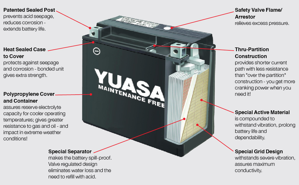
What is a Battery Made Of?
Grids
As the positive and negative electrodes are made of weak materials, they need a mechanical support which is provided by a grid made from a lead alloy; lead on its own would be too soft.
In addition to providing a support for the electrodes (the active material), the grid also conducts electricity from the electrodes to the outside load.
Electrodes
The electrodes are initially made from a mixture of lead oxide and lead sulphate. This is converted into lead dioxide in the positive plate and porous lead in the negative plate when the battery is initially charged.
The negative electrode also contains small amounts of additives to give the battery a good discharge performance at low temperatures to improve starting.
The combination of grid and electrode is normally called a plate.
Electrolyte
The electrolyte is dilute sulphuric acid. This acts as a conductor to transport electrical ions between the positive and negative plates when the battery is being charged or discharged.
The acid also takes part in the discharge as the sulphate ions react chemically at the electrodes to produce lead sulphate.
Separator
The separator is an insulator placed between the positive and negative plates to prevent them shorting together.
The separator needs to be microporous with very small holes to allow the ions to flow through the separator from one plate to another. It also needs to be able to resist the high temperatures and strongly acidic oxidising conditions that occur in a battery.
Most modern separators are made of microporous polyethylene, which has the right properties to meet the demanding conditions within the battery.
Container and Lid
These are normally made of polypropylene, which is a light but strong plastic. Unlike some plastics, it does not become brittle when it is cold, and so can resist knocks during handling. It is not attacked by acid and it can also withstand the fluids (petrol, diesel, brake-fluid, antifreeze) normally found on a vehicle.
What Makes a Battery Maintenance-Free?
30 years ago, batteries lost water at a high rate, and motorists were advised to check the acid level as one of their weekly checks; modern maintenance-free batteries need no water addition throughout their life under normal operating conditions. Incidentally, during the same period, battery life has doubled from 2 years to 4-5 years.
In the past, battery grids were made of an alloy of lead with 10 per cent of antimony; the purpose of the antimony was to give rigidity as pure lead would be too soft on its own. Unfortunately, some of the antimony dissolved in the acid and resulted in the battery losing water.
With improvements in battery technology, we have been able to reduce the antimony content from 10 per cent to 1.5 per cent, and this reduction has resulted in batteries that are low maintenance, needing only yearly attention.
The latest improvement has been the use of 0.1 per cent of calcium as a hardening agent in grids in place of antimony; this causes less contamination of the acid and much reduced water loss, making the battery maintenance-free so no water needs to be added during its operational life.
Service Problems
Overcharge
Modern car charging systems allow only a small current to flow into the battery when it is fully charged. If there is a fault in the alternator, a much higher current will pass through the battery all the time that the car is running. This current will cause the battery to lose water rapidly, destroying the maintenance free characteristics of the battery, and will also reduce the life of the battery by damaging the positive grids.
A dark brown/black colour on the bottoms of the vent-plugs is a strong sign of overcharge.
If an alternator (non Start-Stop vehicle) has a voltage above 14.8 Volts at normal temperatures, this is a generally sign that the charging system is faulty. The common diode fault in the rectifier will see charging voltages of 16.0V at the battery, the alternator should be repaired immediately to prevent any further damage to the battery.
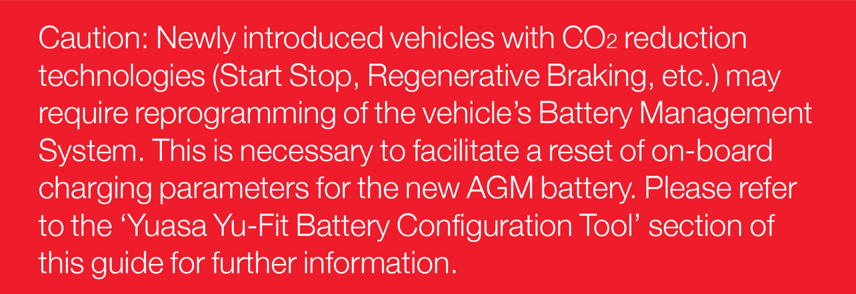
Note with latest Start-Stop vehicles with Brake Energy Regeneration, higher voltages (15.2V) are used to maximise charging efficiencies and reduce alternator charging periods.
Deep Cycling
Modern charging systems keep the battery in a high state-of-charge while the car is running under most operating conditions. However, the battery will discharge under abnormal conditions or if the car is allowed to stand with a load on, for example, lights. On modern cars when parked, there is normally a constant drain on the battery caused by such components as the computer, alarm system, clock etc, and this will cause the battery to become discharged. Depending on the vehicle, this can take weeks or months.
Vehicle batteries are designed to accept some cycles of discharge and recharge, but are not designed for applications in which there are constant cycles of charge and discharge (deep cycling). Leisure batteries have been designed for these types of application, and have a special construction to enable them to be deep cycled on a continuing basis.
Continual deep cycling of vehicle batteries will cause failure as the positive active material will gradually fall to the bottom of the battery, reducing the ability of the plates to store electricity.
A large number of small black/brown particles in the electrolyte are a strong indication that the battery has been deep cycled.
Sulphation
Sulphation is a normal part of the operation of a battery and occurs whenever a battery is discharged. When the battery is recharged, the sulphation (lead sulphate) is changed back into active material.
If a battery is left flat for a period of time, this sulphation slowly changes its form into one that cannot be changed back into ?active material on charging, so, after charge, the battery will not return to give its original performance. If the sulphation is bad enough, the car will not start. This is the problem normally referred to as sulphation.
Undercharge
Undercharge occurs if the battery is not receiving enough charge to return it to a full state-of-charge; this will slowly cause sulphation. This fault can occur if the car is being used only occasionally for short journeys, or for Start-Stop urban motoring. Undercharge will also occur if the alternator voltage is in the region of 13.6 – 13.8 Volts .
Click here to purchase Yuasa Car & Van Batteries - Yuasa Car & Van Batteries
Published: 03/05/2024
All you need to know about Car Batteries
Date Coding of batteries for stock rotation purposes
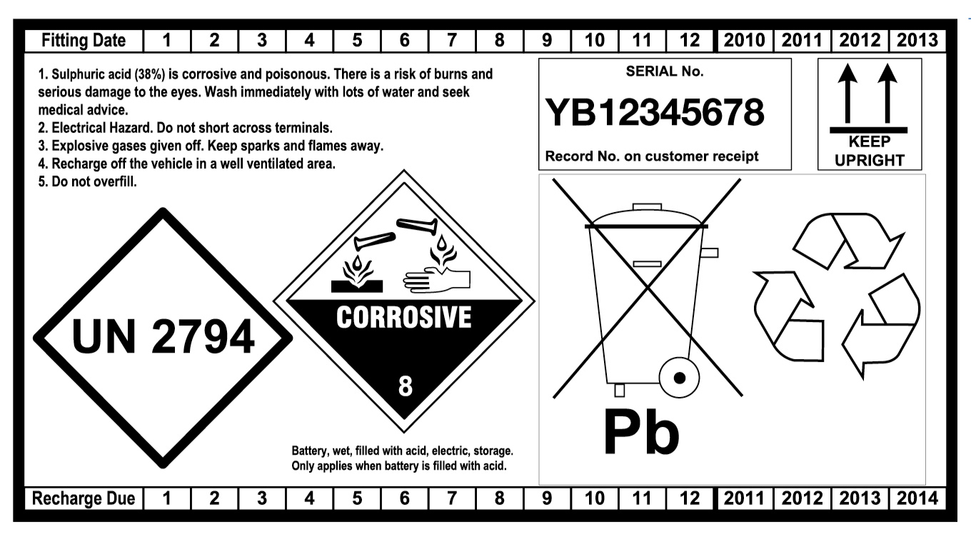
A -Storage
- Always rotate your stock. Practice FIFO (First In, First Out). Batteries slowly lose their charge, and good stock-rotation stops batteries going flat in storage and makes sure that the customer buys a good battery. On the back of the battery there is a label showing the expected period before the battery will require recharging. This makes it easy to identify the oldest and newest batteries in stock. Please use the recharge date to ensure that the oldest batteries leave your stock first. Recharge date is only an indication of recharge period as self discharge is subject to storage conditions.
- Store batteries in a cool, dry, well-ventilated area.
- Protect batteries from excessive heat. (Heat causes batteries to lose charge more quickly, and excessive heat can damage batteries).
- Store batteries in an upright position. (To stop them falling over or leaking).
- Do not stack batteries on top of other batteries. (To avoid scratching, and tearing labels. To avoid damaging terminals that stand proud of the lid).
- Store shrink-wrapped batteries up to 3 high. (Any higher and there is a risk of them falling over and injuring people).
- Do not remove any seals from dry-charged batteries until you are ready to commission the battery by filling it with acid. (The seal preserves the charge in the battery. If it is broken, air will enter and cause the battery to lose charge).
- Store batteries on racks or on pallets, not on the floor. (Small stones or sharp points on a concrete floor can damage the base of the battery and cause leakage).
- Make sure handles are left in the flat (down) position. Upright handles are more likely to be damaged.

B -Maintenance of Stock Handling and Recharging of Batteries
WET Charged Batteries
1. Batteries should be installed ideally within 15 months after manufacture. The voltage should be (worse case higher than 12.25V) ideally higher than 12.4V at the time of installation.
2. Batteries require recharging when the voltage has dropped below 12.4V due to extended warehouse storage. All safety precautions should be undertaken prior to recharging batteries. If a battery has been recharged, the recharge date on the back label should be updated by 6 months after second recharge date by physically notching the label. (Note a maximum of two recharges are allowed prior to sale, and product should not be sold a maximum of 9 months after the expiry of first recommended recharge date).
2.1 A voltage check should be carried out as a matter of course, both to identify older stock and highlight batteries requiring recharge.
2.2 Use a digital voltmeter/multimeter with a minimum of 2 figure resolution (e.g 12.76V).
2.3 Scrap any batteries below 11.0V as these batteries will have developed sulphation that cannot be completed reversed by charging and so will not give the expected performance and life to the customer.
2.4 Note Digital Conductance testers (such as Midtronics and/or Bosch BAT121) are:-
- NOT designed for the testing of new batteries.
- Digital battery testers are not designed to check the fully developed cold cranking performance of a new battery.
- They are designed purely for the testing and evaluation of faulty or used batteries.
- Any CCA/state of health reading from the test on a new battery CANNOT be a reliable guide as to specification of the battery.
See comments on Digital Conductance testers below.
DRY Charged Batteries: Maintenance of Stock
Sales of dry charged batteries within our range is very limited, usually for specialist markets.
- If you keep the batteries cool and dry, and do not remove the seal, dry-charged batteries do not need any other attention.
- The maximum storage time of dry-charged batteries before they are commissioned by filling with acid is 24 months.
- If the seal is damaged, the batteries should be wetted up immediately and the product then treated as WET CHARGED batteries.
- Only commission a dry-charged battery when it is needed for a customer.
- If fitted, remove and discard any sealing plugs, tape or foil.
- If fitted, remove and keep normal vent-plugs and terminal covers (usually red and black).
- For filling, use battery-grade dilute sulphuric acid of specific gravity 1.270 – 1.280 at 25°C conforming to BS3031 or better. (Note: contaminated acid with impurities can seriously damage the life of the battery, in some cases reducing this to a few days. Do not use acid from old batteries).
- The temperature of the acid and the battery should both be at room-temperature in the range 15 – 30°C.
- Fill each cell with acid to a level of 3 – 6mm above the tops of the separators. Fill each cell one after the other and complete the filling in one operation.
- Leave the battery for 20 – 30 minutes and then measure the open-circuit voltage. If it is below 12.50V, charge the battery. If it is above 12.50V, adjust the acid-levels to the correct operating levels with dilute sulphuric acid of specific gravity 1.270 – 1.280. (See Section D below).
- Fit the normal vent-plugs and terminal covers.
- Wash the battery with hot water and dry it.
- Note that performance checks on newly-commissioned dry-charged batteries with modern electronic digital testers using conductance technology are not recommended. Examples are testers supplied by Midtronics or Bosch. The results can be misleading until the battery has undergone some service use.
D -Electrolyte-Levels (Acid-Levels) in Service
Notes: Please read before adjusting acid-levels.
- Do not top up to the maximum levels a battery that needs charging. (Levels rise on charging). However, if the levels are below the tops of the separators, top up with distilled or deionised water until the separators are just covered.
- Adjust levels to the maximum levels only after the battery has stood for at least an hour after charging.
- Never overfill a battery. (The acid may come out of the vent-plugs when the battery is being charged).
- Use only distilled or deionised water for topping up as Sulphuric acid should never be used except for the initial filling of a battery. Do not use bottled Mineral water (impurities within the water will increase water loss and battery self-discharge).
- When the battery is in service, the electrolyte levels should be checked and adjusted to the levels given below.
- If the battery has a maximum level line on the side of the container, fill to this maximum level.
- If there is no maximum line, but there are filling tubes projecting from the bottom of the lid, fill to the bottom of the tubes.
- If there is not a maximum line nor filling tubes in polypropylene batteries, fill to 7mm (0.25 inches) below the bottom edge of the lid-skirt.
- If there are no filling tubes in hard-rubber batteries, fill to 15mm (0.5 inches) above the tops of the separators.
E -Selecting the Correct Battery for the Application
Car and Commercial Vehicle (CV) Batteries
- Select the specified battery from the Yuasa trade Online Vehicle Battery Lookup Tool.
- On 24 Volt systems, or when 2 off 12 Volt batteries are fitted in series, both batteries should be replaced at the same time. Failure to do this will result in a greatly reduced battery life for the new battery that has been fitted. When batteries are joined in series, the negative terminal of one battery is connected to the positive terminal of the other, giving a total voltage of 24 Volts. The Ampere-hour capacity of the system is the same as that of the individual batteries. When batteries are joined in parallel, the positive terminals of the 2 batteries are connected together, and the negative terminals of the 2 batteries are also connected together. The voltage of the system remains unchanged at 12 Volts, but the Ampere-hour capacity of the system is double that of the individual batteries.
Leisure Batteries
- Use the battery with the performance and size recommended by the equipment supplier.
- We recommend that a leisure battery in a medium cyclic application should be sized so that it is not normally discharged to more than 50 per cent state-of-charge. This will ensure that the battery gives a good life. The life of a battery regularly discharged by 50 percent is about 5 times that of a battery regularly discharged to 100 per cent. For example, a load of 4A for 10 hours will discharge a battery by 40Ah. If this represents 50 per cent state-of-charge, we would recommend a 80Ah battery.
Marine Batteries
- The Marine battery range has been designed with greater cyclic durability than the Leisure range and principally designed for hotel load usages on boats.
- The Marine battery range has been designed with sealed lid to exceed the 55° duration requirement according to item 5.10 of EN50342.1 A1 2011.
F -Removing Batteries and Installing Batteries on Vehicles
- It is good practice to tell the customer that, while you will do your best to keep the memory settings, it is possible these might be lost.
- Make sure the hand-brake is on, and that the car is in neutral or park. Switch off all electrical loads and remove the ignition key from the car. Note: On some cars, the doors will lock when the battery is disconnected so this is why the key should be removed from the car. Also switch off any non-factory-fitted alarms.
- Check that the cigar lighter is still working. If not, turn the ignition key to the auxiliary position. Install a Computer Memory Saver (CMS).
- Disconnect the earth-connector first. (This is normally the negative on modern vehicles). This can result in the loss of memory settings; please refer to the vehicle handbook.
- Disconnect the live-connector second. If a CMS is used, the connector will still remain live after it has been disconnected. To prevent the connector shorting against the car, place an insulator such as a rubber glove over the connector.
- Remove the hold-down clamps.
Preparation of a Battery for Fitting
- Check that the battery has the correct polarity for the vehicle.
- Check that the battery has the correct height for the vehicle. (If a battery is too high, it can short out on the bonnet or the bottom of a seat, or it can damage the bonnet).
- It is good practice to place the old and new battery side by side to compare polarities, hold-downs and performance-levels. Some batteries have hold-downs at both the sides and ends. Only the ones used for securing the battery on the vehicle need to be checked.
- Check that the battery is clean and dry.
- Check that the vent-plugs or manifolds are firmly in position.
- Check that the battery has a voltage above 12.40V. If not, charge the battery or use another that has a voltage above 12.40V.
- Ensure the 2 terminal caps are still fitted at this stage.
Preparation of the Vehicle
- Clear away any items on the battery-tray which might damage the battery. (Placing a heavy battery on a piece of sharp grit can puncture the bottom of the battery).
- Check that the connectors, the hold-down clamps and the tray are clean and corrosion-free. (If there is any corrosion, hot water will instantly remove this). If there is severe corrosion which might affect the stability of the battery or has affected other parts of the engine compartment, have the vehicle checked by an authorised distributor.
- Check that the alternator drive-belt tension is correct. Refer to the vehicle handbook or service manual.
- It is recommended that the electrical system, and particularly the charging system, of the vehicle be checked to make sure it is operating correctly. Refer to the vehicle handbook or service manual.
Installing the Battery
- Fit and tighten the hold-down clamps. These should be tight enough to secure the battery and not allow it to move. DO NOT OVERTIGHTEN.
- Connect the live-connector first to the correct battery-terminal (normally the positive) after removing the terminal cap. DO NOT OVERTIGHTEN.
- Connect the earth-connector to the other terminal after removing the terminal cap. DO NOT OVERTIGHTEN.
- Place the 2 terminal caps on the old battery that has been removed from the vehicle to avoid the possibility of short-circuits.
- Replace onto the new battery any components that have been taken from the old battery such as exhaust tubes, vent-elbows, terminal covers, removable hold-down strips (widgets) etc.
- The use of petroleum-jelly (Vaseline) is not necessary on modern polypropylene batteries, but there is no disadvantage in using it. Smear lightly on the terminals. It is still recommended for hard-rubber batteries. Do not use grease.
- Remove the CMS.
- Start the engine
- For non-automotive applications, install the battery in line with the equipment-supplier’s recommendation.
G -Charging Off-Vehicle
Note: Please read before charging batteries
- Do NOT charge a battery if its temperature is below 3°C as the electrolyte may have frozen.
- Charging the battery on the vehicle is not recommended.
- Refer to Section F for information about removing the battery from the vehicle.
- ‘Sealed and AGM’ vehicle batteries should be charged only on constant potential chargers or ‘smart’ chargers. Do not charge on constant current chargers or boost chargers.
- ‘Sealed’ vehicle batteries do not allow any access to the electrolyte, and so cannot be topped up. There are no removable vent-plugs or manifolds. The battery is able to vent gases through breathing holes, and so it is not strictly sealed.
- A new, unused battery with a voltage below 11.00V should be scrapped and not charged. See Section B.
General Procedure for All Types of Chargers
This section gives common information for all types of chargers. The sections below give details for different types of charger.
- 1.Check the electrolyte-levels in all the cells. If these are below the tops of the separators, top up with distilled or deionised water to the tops of the separators. Do not fill to a higher level before charging, but adjust the levels after charging. See Section D.
- If you are using a constant-current charger or a boost-charger, remove the vent-plugs or manifolds before charging. (See below). There is no need to remove the vent-plugs or manifolds if you are using a constant-potential or a ‘smart’ charger.
- Check that the charger is switched off.
- When fitting the charger to the battery, connect the positive lead to the positive terminal and the negative lead to the negative terminal.
- Switch on the charger. See below for the correct charging conditions depending on your type of charger.
- Stop charging if the battery begins to gas freely (some gassing is normal during the last stages of charging) or if the battery temperature rises above 50°C.
- Switch off the charger.
- It is good practice to wait for about 20 minutes for the gases to clear before removing the leads from the battery as some chargers remain ‘live’ and can cause a spark.
- Check the electrolyte-levels in all the cells and top up if necessary. See Section D.
- Refit vent-plugs or manifolds if these have been removed.
- Wash the battery with hot water and dry it.
- Note. Many customers severely underestimate the amount of time necessary to charge a flat battery. This results in customers returning batteries saying that they have charged the battery but that it is still not holding charge.
Types of Charger and How to Use these
There are many types of charger available; their working principles and the procedure for using these is given below.
Index
| Section | Charger Type |
| 1. | Constant Current Chargers |
| 2. | Constant Potential Chargers |
| 3. | Modified Constant Potential Chargers |
| 4. | ‘Smart’ Chargers |
| 5. | Boost Chargers |
1. CONSTANT CURRENT CHARGERS
These maintain a fixed, constant, preset current throughout the charging period irrespective of the battery on-charge voltage. Do not charge AGM batteries on a constant current charger.
Charging Procedure with Constant Current Chargers
A.Ideally, charge each battery on a separate charger unit. If this is not possible, charge batteries in series. We do not recommend charging batteries in parallel because it is not possible to control the amount of current passing through each battery.
If batteries in different states-of-charge are being charged in series, each battery should be removed as soon as it is charged. (If you wait until the last battery is charged, some of the batteries will be overcharged).
B.Measure the open-circuit voltage of the battery. To obtain a stable voltage, the battery should not have been used or charged for a minimum of 3 hours before checking the voltage.
C.Charge the battery at the recommended charge rate (See Battery Specifications section of the Catalogue). If you cannot set the recommended rate, extend or reduce the charging time on a pro rata basis.
For example, if the recommendation is to charge the battery at 4.0A for 6 hours (24Ah = 4.0 x 6), charge the battery for 12 hours if you can only set the charger at 2.0A (24Ah = 2.0 x 12).
D.Charge the battery for the number of hours shown in the table below depending on the open-circuit voltage.
For example, if the battery has a voltage of 12.16V, charge it for 10 hours at the recommended charge rate.
| OPEN-CIRCUIT VOLTAGE (V) | CHARGING TIME (HOURS) |
| Above 12.40 | 4 |
| 12.31 – 12.40 | 6 |
| 12.21 – 12.30 | 8 |
| 12.11 – 12.20 | 10 |
| 12.01 – 12.10 | 12 |
| 11.91 – 12.00 | 14 |
| 11.81 – 11.90 | 16 |
| 11.71 – 11.80 | 18 |
| 11.00 – 11.70 | 20 |
| Below 11.00 | See paragraph E below |
E.If you are charging a battery below 11.00V (overdischarged) that has been in service, a specialised charger capable of providing a very high charging voltage may be necessary, and the recommended current may not be obtainable at first. In this case, monitor the current and adjust as necessary during the charge.
If a battery has become overdischarged, it will have lost both life and performance because of irreversible sulphation. Charging may reduce further its potential life.
2.CONSTANT POTENTIAL CHARGERS
These maintain a fixed, constant, preset voltage throughout the charging period. The current cannot be set and will fall as the battery state-of-charge increases.
Charging Procedure with Constant Potential and Modified Constant Potential Chargers.
A.These chargers are normally designed to charge one battery at a time.
B.Stop charging when the battery is gassing freely and the battery-voltage shows no increase over a period of at least 2 hours.
C.Note. The majority of constant potential chargers are incapable of charging a severely overdischarged (below 11.00V) battery in a realistic period of time. A minimum of
24 hours is normal.
It might be impossible to charge an overdischarged battery.
3.MODIFIED CONSTANT POTENTIAL CHARGERS
The majority of commercial chargers, particularly home-chargers, are of this type, and allow neither the voltage nor the current to be preset.
Charging Procedure with Modified Constant Potential Chargers.
A.Use the same procedure as for Constant Potential Chargers in the paragraph above.
4.‘SMART’ CHARGERS
The latest generation of chargers is able to check the battery condition, and to supply automatically a controlled charge that will charge the battery in the fastest time without damaging it and without overcharging it at the end of the charge. Some ‘smart’ chargers have a special setting for all-calcium batteries and will charge these from flat, which most other chargers are unable to do.
Charging Procedure with ‘Smart’ Chargers
A.Follow the manufacturer’s instructions.
B.These chargers should be able to charge overdischarged (below 11.00V) batteries. Note that some have a special setting for all-calcium batteries.
5.BOOST CHARGERS
These provide a very high initial current, and are used mainly to put some charge into a flat battery when it is needed urgently by the customer. The current falls as the battery state-of-charge increases, and the battery temperature is monitored to make sure it does not overheat.
Charging Procedure with Boost Chargers
A. Boost charging is not recommended except in exceptional circumstances eg a stranded customer, as this will reduce battery life, especially if a battery is boost-charged more
than once.
B.Never boost-charge any battery that is below 11.00 Volts as it will be too sulphated to accept a charge; scrap the battery or charge normally.
C.Only use a boost-charger that limits the charging voltage to a maximum of 14.2 Volts and that has a temperature monitor.
D.Follow carefully the charger-manufacturer’s instructions.
H -Checking Battery Performance
Electronic Testers Using ConductanceTechnology
- The latest generation of testers is digital. Examples are Midtronics and Bosch testers. These will give an immediate decision on about 80 per cent of batteries in service, including flat ones. In the remaining 20 per cent of cases, the batteries need recharging before testing.
- These testers show whether the battery is in a good, charged condition, whether it is discharged or whether it needs replacing.
- Note. This is the preferred method of checking batteries as it does not take any charge out of the battery. It is also easier, quicker and safer.
Digital Conductance Testers Explained
As reported by most battery manufacturers, some confusion has been created within the battery industry regarding the apparent performance of batteries after tests conducted with digital conductance testers (e.g. Midtronics, Bosch BAT121 being the most common types currently on the market).
It is important that the purpose of these tester is clearly understood.
Digital conductance battery testers are not designed to check the cold cranking performance of a new battery.
They are purely designed for testing and evaluation of suspect or used batteries. Any CCA or state of health reading from the test CANNOT be a reliable guide as to the specification of the battery.
The BCI and European EN standard as a testing benchmark for manufacturing process.
Yuasa Batteries (part of the GS Yuasa Corporation) is one of the largest manufacturers worldwide of Lead acid Automotive batteries and its batteries are designed to confirm to the internationally recognised standards.
For example, the initial performance testing procedure according to the EN50342.1 A1 Nov 2011 requires a minimum of 12 working days of testing and significant resources in equipment to validate batteries. All Yuasa branded batteries sold into the market and regularly audit tested to ensure conformance to the relevant standard.
The EN 50342 standard has created further confusion in the market by listed two conformance level standard for high rate cold cranking performance which are not clear to the end user without full access to the ETN part number listing.
EN1 Test @ -18°C 10s to 7.5V, 10 seconds rest than 60% of current to 6V where time should be greater than 73s.
EN2 Test @ -18°C 10s to 7.5V, 10 seconds rest than 60% of current to 6V where time should be greater than 133s.
The rating of the battery obviously varies subject to battery design, but for example a battery rated at 1000A according to EN1, could only be rated at 920A according to EN2. The information of which standard the battery is rated is currently held within the ETN number e.g. 550 034 050<
550=> 12 Volt 50Ah battery
034=> Is a specific number to that battery which gives details of lid type, life, vibration resistance and also whether the battery conforms to EN1 or EN2 high rate
050=> High rate current in this case 500A
There are currently nearly 2000 individual battery numbers listed on the ETN data base by different battery manufacturers and users. This currently makes it unclear to the customer to what rating the battery is capable of meeting EN1 or EN2 without access to the listing.
In order to minimise confusion, Yuasa currently use the longer established American BCI SAE rating for cold cranking amps which is the current to deliver 30 seconds to 7.2V at a temperature of -18°C. This is seen as a fairer comparison to give a balanced view of the batteries durability and starting performance.
The evolution of the Conductance tester into the market
In the last ten years, comparatively inexpensive conductance meters have entered the market which are able to determine the specific internal resistance of an automotive battery using the principles of the AC Wheatstone bridge (which you may remember from school days). The clear advantage of these devices is that they are portable, easily operated, no sparking risks from carrying out traditional high rate load “drop” test and deliver results in just a few seconds.
Disadvantages
The disadvantage of the conductance tester is that they all use a standard algorithm (program) to estimate the CCA reading from the measured internal resistance reading. The values given by these meters are not comparable with those determined using the laboratory test equipment where batteries are physical discharged under real high discharge load, at a temperature of -18°C. Due to differences in battery designs it is not possible to give a perfect relationship between internal resistance and actual performance in the laboratory.
Laboratory testing shows that the algorithm used in conductance testers penalises batteries where the battery design has been optimised (with heavier high density, fine porosity plates) for durability/cyclic endurance than those designs optimised for high rate performance.
For the evaluation of new factory fresh batteries different readings can be seen depending on the manufacturers plate design and acid density. Even significantly different readings can be obtained between different brands of tester. Expanded plates give a higher reading than a cast plate, as the cast plate has a full frame construction for improved conductivity. The grid size can be reduced and made thicker to access the active materials toward the bottom of the plate. This design difference for example has a difference on the conductance readings where the tester correlates to the CCA reading based on a standard formula. The testing of new batteries is more complex as testing under the EN50342 standard requires the battery to be conditioned after a number of cycles which alter the conductance of the paste and hence causes more variation in tester data produced.
For this reason, Yuasa and other major battery manufacturers recommend that the confirmation of the compliance of unused batteries to the EN or BCI can only be determined using laboratory testing and that digital conductance tester are not suitable to evaluate the performance of new unused batteries.
Conductance Tester are designed to measure the internal resistance of the battery. The testers effectiveness on a deeply discharged battery is less effective as although a good starting current figure can be indicated and the vehicle will start, it does not indicate that the 20 hour capacity of the battery may be as low as 10-30%. due to repetitive operation in low states of charge. It is suggested that if this is suspected, the battery should be tested after the lights have been left on for 15 minutes without the engine running.
Open-Circuit Voltage and High-Rate Discharge Testers.
- Measure the open-circuit voltage of the battery using a digital voltmeter or a multimeter. To obtain a stable voltage, the battery should not have been used or charged for a minimum of 3 hours before checking the voltage.
- If the voltage is below 12.40V, charge the battery in accordance with Section G. Note. This type of tester will only give an accurate result on a fully-charged battery. A common mistake is to use this type of tester on a discharged battery, and to judge that the battery is faulty if a cell is seen to ‘boil’. A ‘boiling’ cell on a flat battery does not mean that the battery is faulty.
- Apply a current-load equal to half the SAE CCA cold cranking Amps for 15 seconds. For example, discharge a 600A battery at 300A. Observe the voltage during this time and record the voltage after 15 seconds. You will find the CCA in the Battery Specifications section of the Catalogue or on the label. Use an approved, calibrated tester.
- If the voltage after 15 seconds is stable and above 9.60V, the battery is in a satisfactory condition with no faults.
- If the voltage is below 9.60V after 15 seconds and it is unstable, normally falling quickly, the battery should be replaced.
‘Drop Testers’
- ‘Drop testers’ have 2 spikes that are pressed into the tops of the battery terminals and a simple voltmeter to check the discharge voltage.
- We do not recommend the use of these testers as:
- They are potentially unsafe to use as most types produce a spark when the spikes are first pressed into the terminals.
- The discharge rate is similar for all sizes of battery, and so they do not give a good indication of battery-condition.
- They give misleading results on discharged batteries.
I -Maintenance in Service
General
1 .Always refer to the information contained in the handbook or brochure supplied with the vehicle or equipment.
Definition of Maintenance-Free
- 1.Our starter batteries for cars and commercial vehicles conform to the relevant sections of EN50342.1 A1 Nov 2011 for maintenance-free characteristics. This means that in normal vehicle applications in temperate climate operation, it is not necessary to add water.
- Our batteries are designed to be topped up with water if water should be lost owing to, for example, a charging system fault, prolonged operation in hot climates, excessive off-vehicle charging etc.
- Note. The term maintenance-free applies only when the battery is used in an approved automotive or commercial vehicle application.
Definition of Low Maintenance
- Low maintenance batteries in normal vehicle applications in temperate climate operation need water-addition only at yearly intervals.
- Our batteries are designed to be topped up with water if water should be lost owing to, for example, a charging system fault, prolonged operation in hot climates, excessive off-vehicle charging etc.
- Note. The term low maintenance applies only when the battery is used in an approved commercial vehicle application.
Battery Maintenance in Automotive Applications
- Carry out the checks below at the recommended vehicle service intervals.
- Check the electrolyte-level and top up with water if necessary. See Section D for details about how to do this. (As explained above, it should not be necessary to add water unless the battery has encountered exceptional conditions).
- Check that the battery is clean and dry and that the vents are not obstructed.
- Check that the terminal-connectors and the hold-down clamps are securely-connected and corrosion-free.
- If the battery is on a vehicle that is not to be used for an extended period (more than 1 month), disconnect it from the vehicle. Refer to Section F for information about removing the battery from the vehicle. Modern cars have electrical accessories that slowly discharge the battery even when the ignition key has been removed. Some accessories such as alarms, trackers, and phones can cause a battery to become discharged in a few weeks.
- Fully charge the battery before storage and give it a refreshing charge every 3 months. See Section G.
Battery Maintenance in Non-Automotive Traction and Deep Discharge Applications
- Typical applications are lawnmowers, electric wheelchairs, caravans etc. The Leisure Battery range is recommended for these applications; standard vehicle batteries are not suitable.
- Ensure that the battery is always kept in as high a state-of-charge as possible. Always recharge immediately after use.
- Check the electrolyte-levels on a regular basis dependent upon use. Charging batteries regularly on a non-vehicle charging system may result in a higher rate of water-loss.
- Check that the battery is clean and dry and that the vents are not obstructed.
- If the battery is not to be used for an extended period (more than 1 month), fully charge it before storage, and give it a refreshing charge every 3 months. See Section G.
Battery Maintenance in Non-Automotive Float Applications
- Typical applications are motor-generators, stand-by applications etc. The Leisure Battery range is recommended for these applications; standard vehicle batteries are not suitable.
- Batteries used in these applications should be changed every 2 years or more frequently. (Continuous charging, even from a well-controlled charging system, will result in internal degradation of the battery. This could result in the battery not giving its predicted output when required even though the battery appears to be fully-charged).
- Ensure that the battery is always kept in as high a state-of-charge as possible without causing excessive overcharge. Always recharge immediately after use.
- Check the electrolyte-level on a regular basis dependent upon use, but not less frequently than monthly. Charging batteries continuously on a non-vehicle charging system may result in a higher rate of water-loss.
- Check that the battery is clean and dry and that the vents are not obstructed.
- If the battery is not to be used for an extended period (more than 1 month), fully charge it before storage, and give it a refreshing charge every 3 months. See Section G.
- Best practice is to define a regular maintenance-routine, and to record the results.
- This should include such variables as the amount of water added to each cell, specific gravities in each cell, battery voltage etc.
Use of Battery Additives
- We do not recommend the use of battery additives.
- The use of these invalidates the guarantee.
Click here to purchase Yuasa Batteries - Yuasa Car & Van Batteries
Our Branches
York Tel: 01904 628828
Malton Tel: 01653 602700
Selby Tel: 01757 403300
Scarborough Tel: 01723 413104
Poppleton Tel: 01904 917280
Harrogate Tel: 01423 223940
Thirsk Tel: 01845 421421


© Copyright 2019 York Motor Factors ~ Head Office: 62 Layerthorpe, York. YO31 7YW ~ Reg number 0955941 Vat reg number 170164586